


Scan-to-CAD & reverse engineering
Scan-to-CAD & reverse engineering services in Montreal
Turn a physical part into an editable parametric CAD model. Our Montreal scanning lab ships and delivers Canada-wide — from legacy components and replacement parts to design iteration on real-world geometry.
±0.1 mm accuracy
ISO 9001 processes
Montreal lab — Canada-wide
Free design review
How scan-to-CAD works
A simple three-step workflow that takes your physical part to a clean, editable CAD file.
01
We capture the full geometry of your physical part with structured-light and laser scanning down to ±0.1 mm accuracy.
02
Mesh cleanup & alignment
Raw point clouds are decimated, aligned, and converted into a clean, watertight reference mesh suitable for modelling.
03
Our engineers rebuild the part as a fully editable parametric CAD model with proper features, datums and design intent.
From physical part to editable CAD
A simple three-step workflow that takes your physical part to a clean, editable CAD file.
Step 1
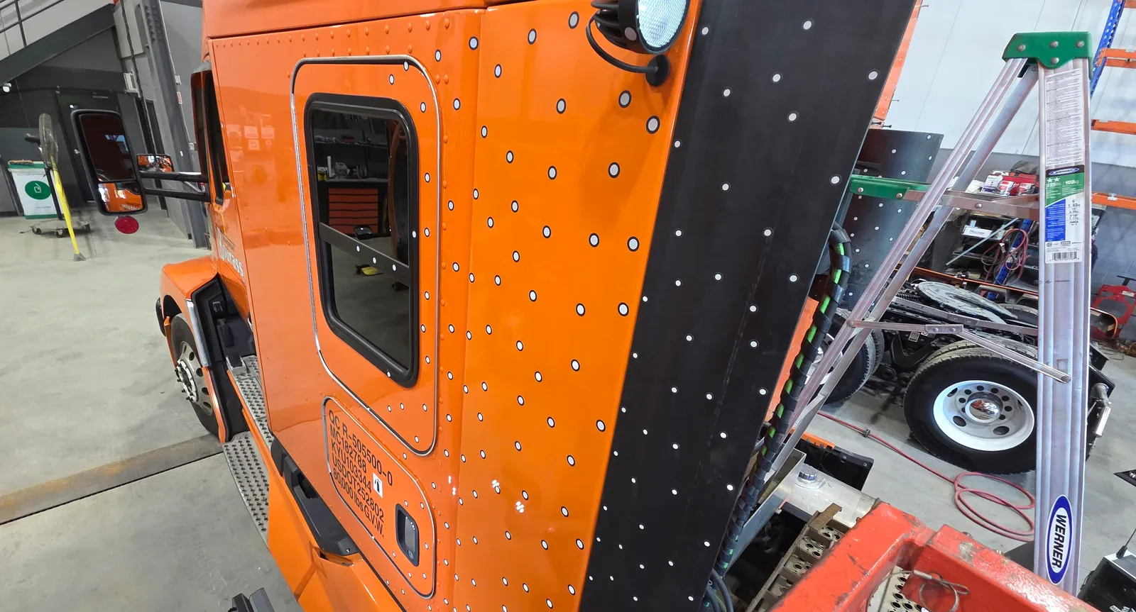
On-Site 3D Scanning
Reflective reference targets applied to a truck cabin for large-format structured-light scanning. We scan parts in place — on vehicles, machinery, or assemblies — down to ±0.1 mm accuracy.
- Step 2
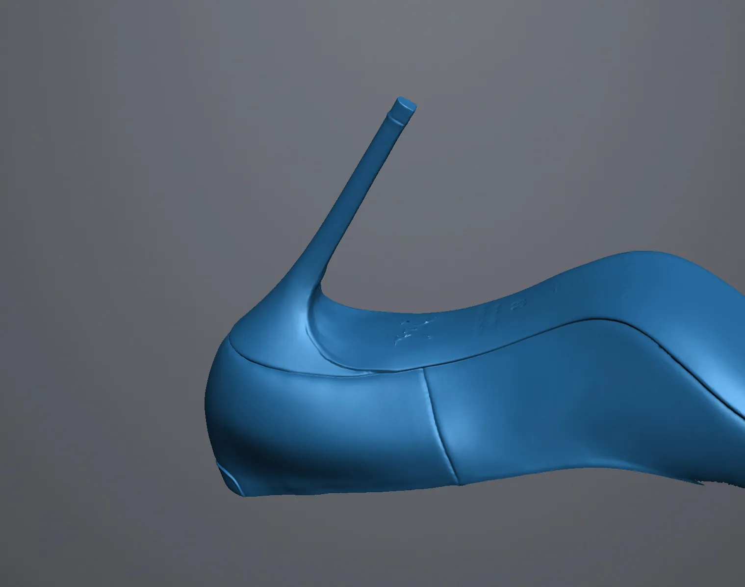
Raw Scan Mesh
A cleaned, watertight polygon mesh captured directly from the physical object. This mesh preserves every curve and embossed detail — the reference geometry our engineers use to rebuild parametric CAD.
- Step 3
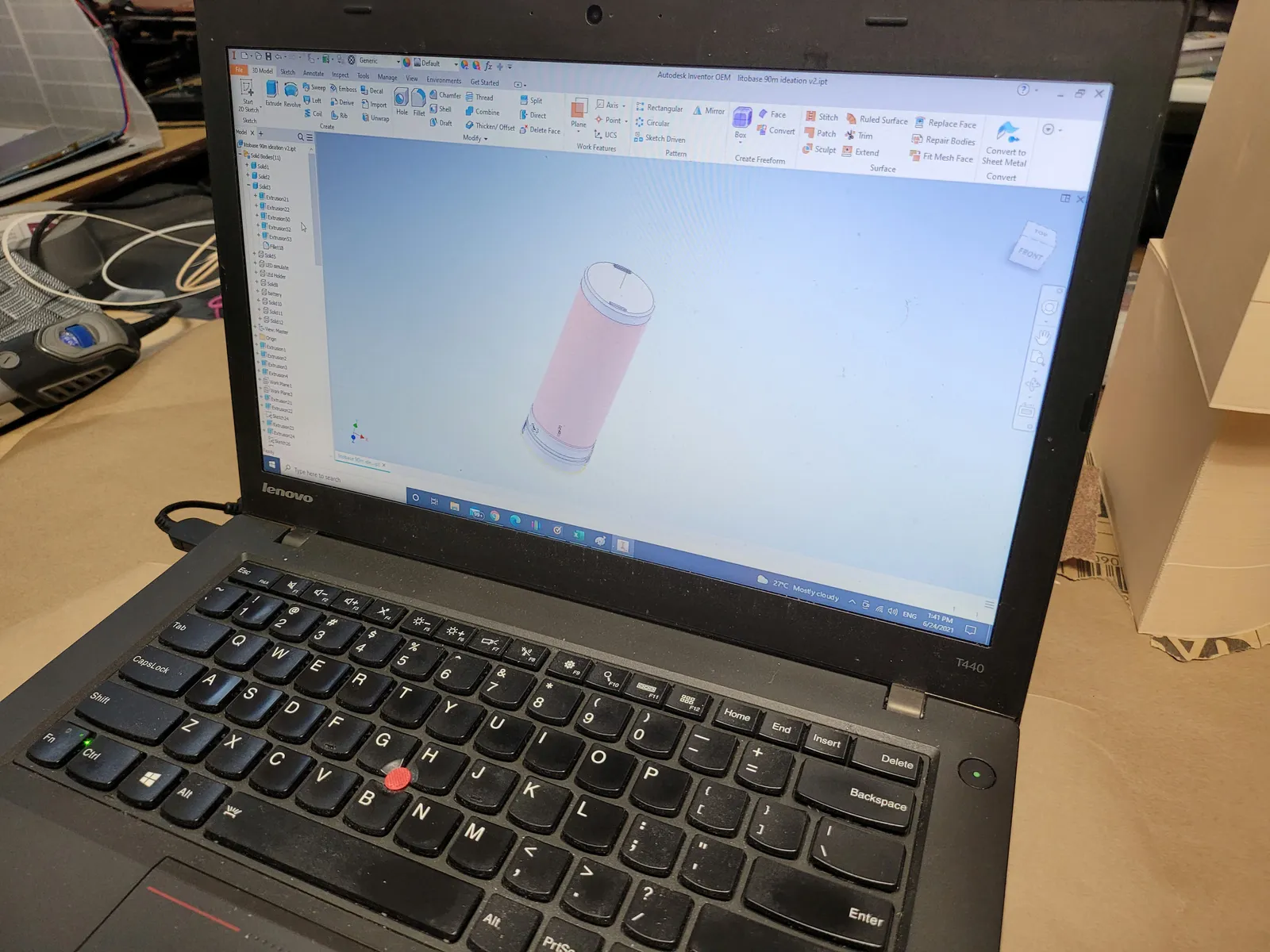
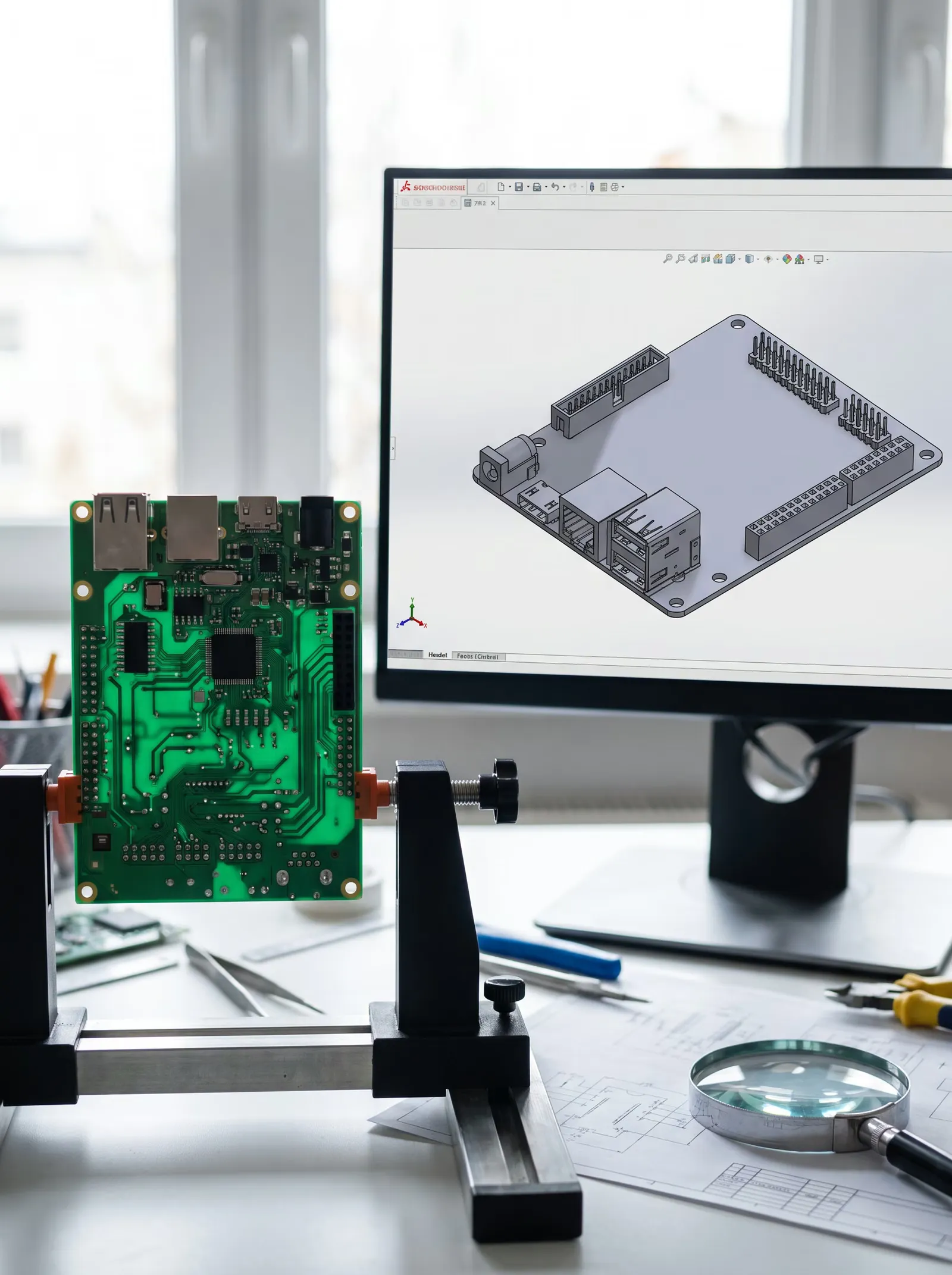
Parametric CAD Rebuild
Rebuilt as a fully editable parametric model in Autodesk Inventor with proper features, sketches, and design intent — ready for engineering changes, drawings, and manufacturing.
- Deliverable
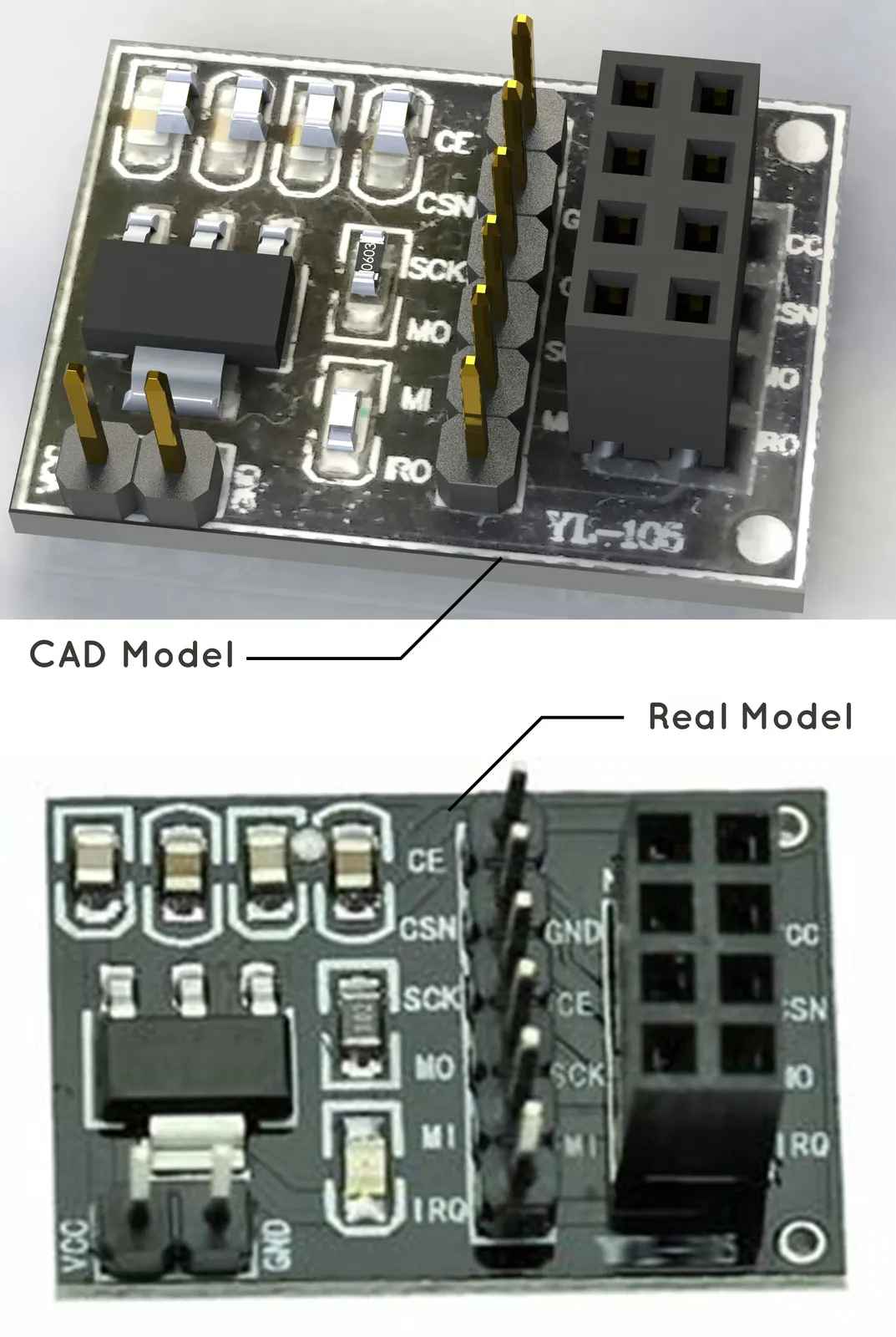
CAD vs. Real Part
Side-by-side comparison of a reverse-engineered PCB assembly against the physical original — geometry, connectors, and component footprints reproduced faithfully in parametric CAD.
When to use reverse engineering
Real-world situations where a scan-to-CAD workflow saves time, cost, and risk.
Obsolete parts
Recreate parts that are no longer manufactured or sourced from suppliers that no longer exist.
No drawings available
Reverse engineer legacy components when original CAD files and 2D drawings are missing.
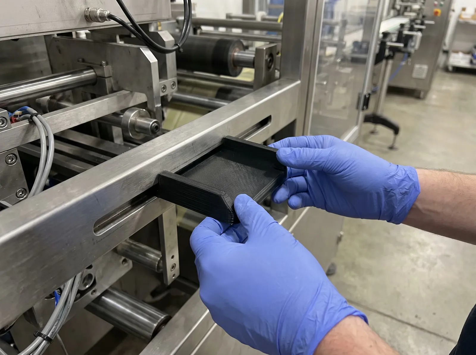
Replacement parts
Produce drop-in replacement parts for machinery, equipment, and out-of-production assemblies.
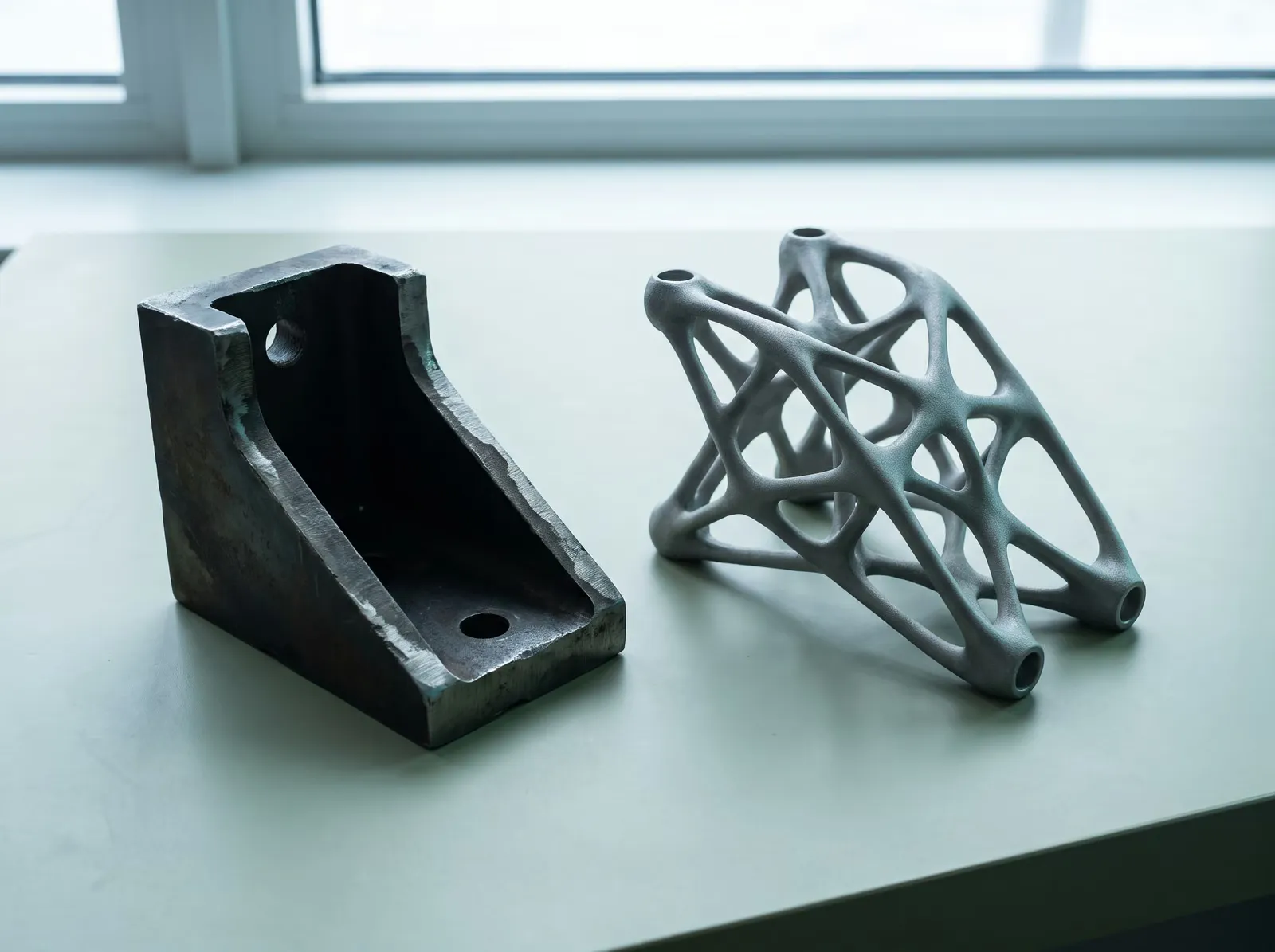
Design improvement
Use a working part as the starting point to optimise geometry, weight, or material.
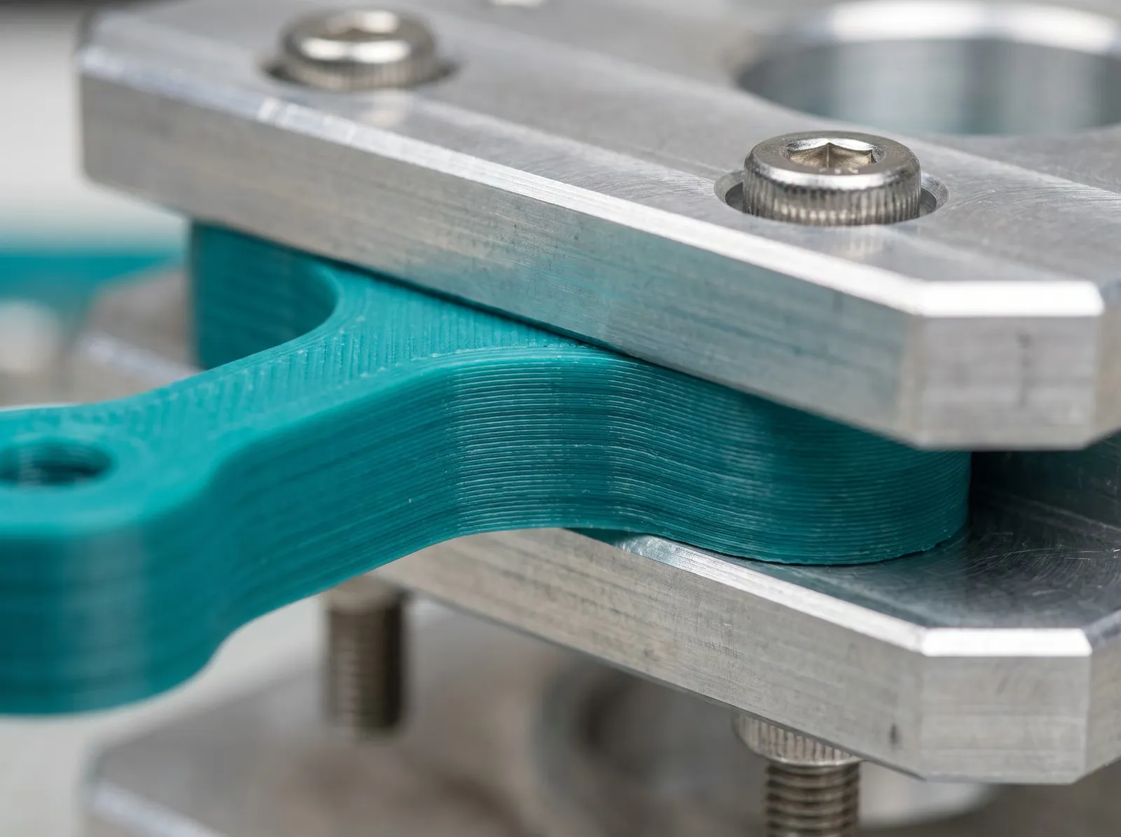
Fit to existing assembly
Capture mating surfaces and interfaces so a new part fits perfectly into the existing assembly.
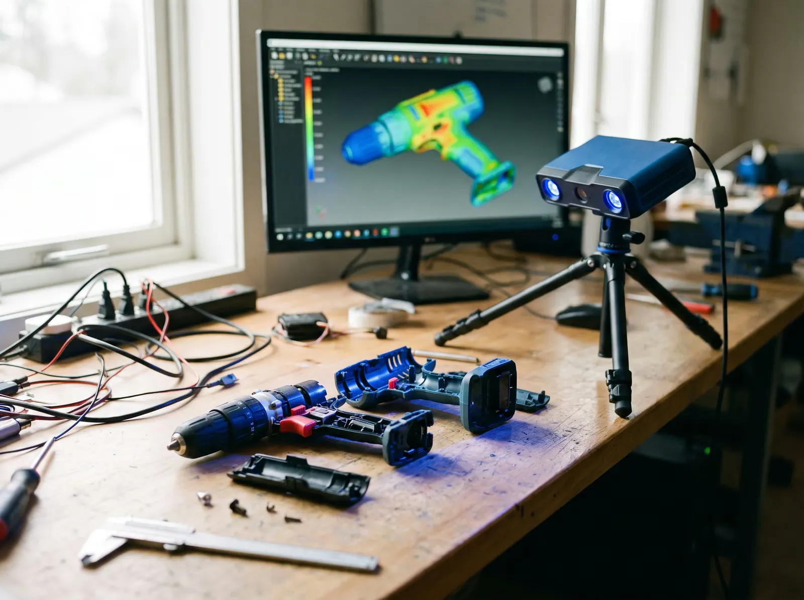
Competitor benchmarking
Digitise competitor products to analyse construction, tolerances, and design choices.
File formats & deliverables
We deliver in whatever format your engineering team works in — parametric CAD for design and manufacturing, mesh for printing and visualisation.
| Feature | Parametric CAD | Mesh |
|---|---|---|
| Editability | Fully parametric — edit features, dimensions, history | Static surface — not parametric |
| Best for | Manufacturing, engineering changes, drawings | 3D printing, visualisation, reference |
| Typical formats | STEP, IGES, SolidWorks (.sldprt), Fusion 360 (.f3d) | STL, OBJ, PLY |
| Tolerancing | Supports GD&T and 2D drawings | Surface deviation only |
| File size | Compact, feature-based | Large, polygon-based |
Industries we serve
Scan-to-CAD and reverse engineering applied across regulated and consumer-facing industries.
Automotive & restoration
Classic car parts, brackets, trim, custom modifications.
Aerospace
Tooling, fixtures, and legacy component reproduction.
Medical
Device housings, custom fixtures, and prototype iterations.
Consumer products
Packaging fit, ergonomic handles, accessory mating parts.
Manufacturing
Jigs, fixtures, replacement machine parts, tooling.
Have a part you need in CAD?
Send us photos, dimensions, or the physical part. Our Montreal team will scope a scan-to-CAD project and reply with a transparent written quote.
Scan-to-CAD vs CAD design — which do you need?
Choose scan-to-CAD when you have a physical part. Choose CAD design when you are starting from an idea.
| Aspect | Scan-to-CAD | CAD Design |
|---|---|---|
| Starting point | Existing physical part | Idea, sketch, or specification |
| Goal | Replicate or modify an existing object | Create a new product from scratch |
| Deliverable | Parametric CAD matching the scanned part | Parametric CAD of a new design |
| Common use | Legacy parts, replacements, fit-up | New product development, custom parts |
Starting from scratch instead? Explore our CAD design services .
Related projects
Parts we scanned, rebuilt in CAD and reproduced.
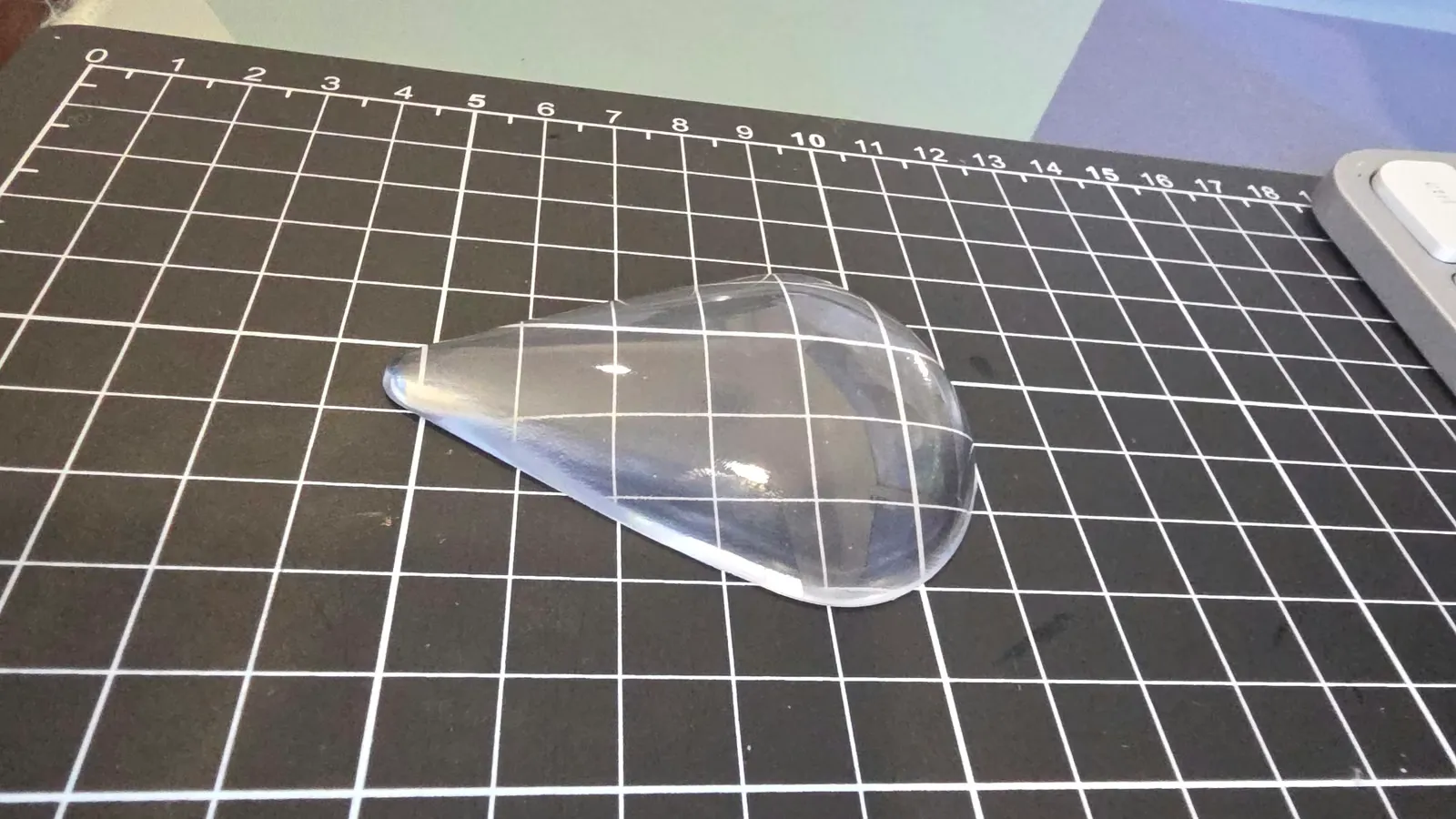
SLA · Industrial
Clear headlight lens covers
Replacement clear lens covers reproduced by 3D scanning the originals, modelling them in CAD, printing them in clear resin by SLA and polishing them.
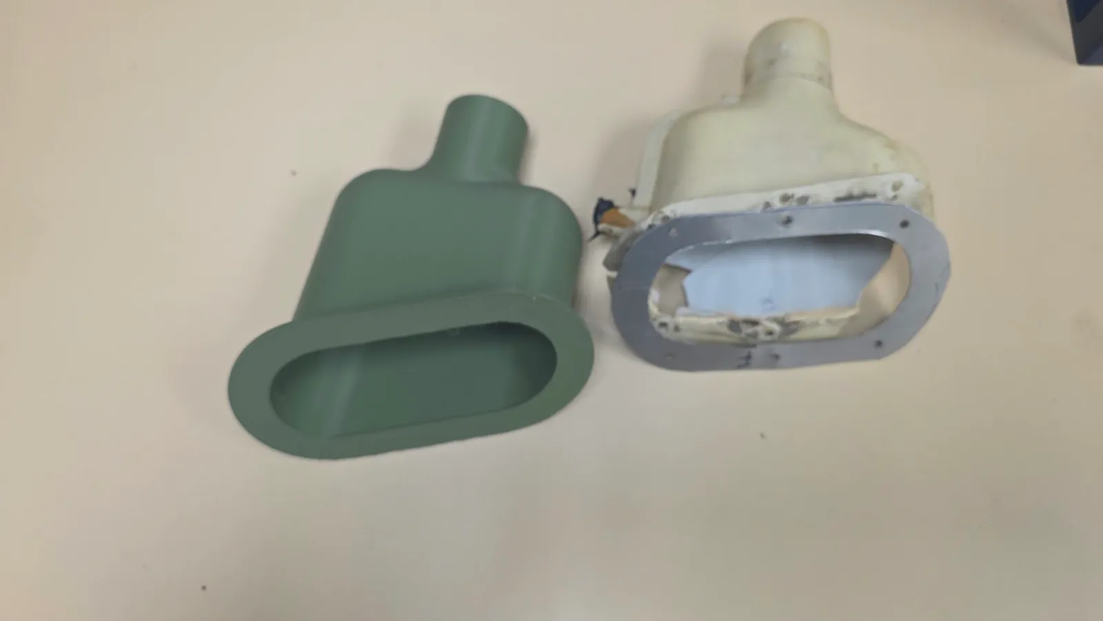
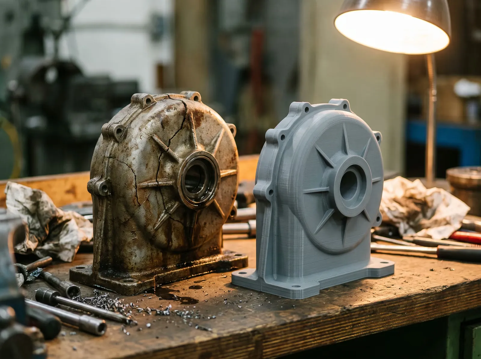
Replacement duct housing
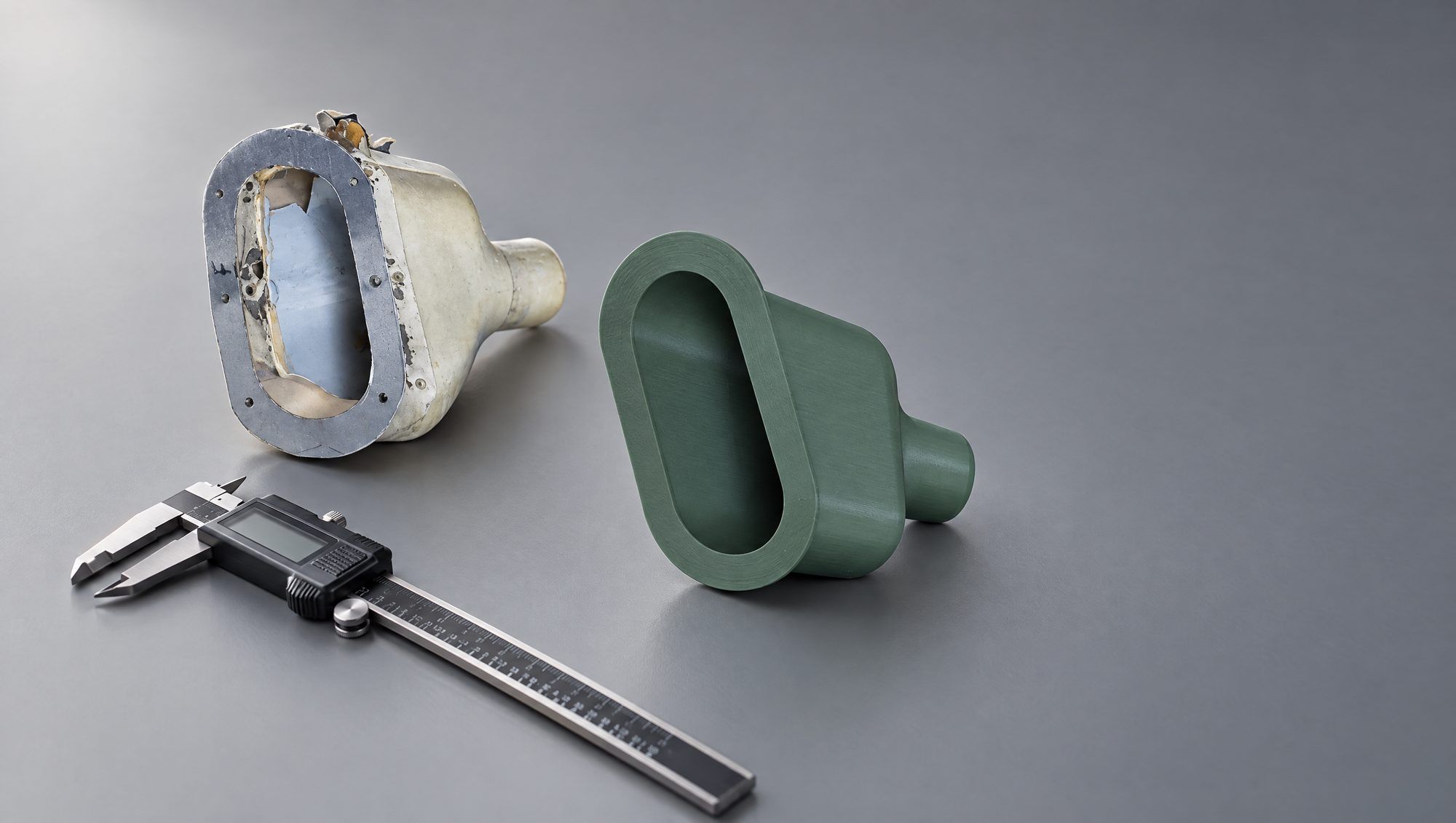
A damaged duct beside its green printed replacement: a practical look at reproducing the overall shape of a physical part.
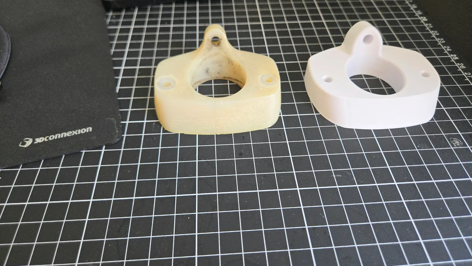
Replacement mounting bracket
An existing flanged part recreated in CAD and as a white printed prototype, with its central opening and mounting points preserved in the model.
Scan-to-CAD & reverse engineering FAQ
What's the difference between a mesh and a parametric CAD file?
A mesh (STL/OBJ) is a static surface made of triangles — great for 3D printing or visualisation, but not editable. A parametric CAD file (STEP, SolidWorks, Fusion 360) is built from features and dimensions you can change, which is what engineering, drawings, and manufacturing require.
Can you reverse engineer a part if there are no drawings?
Yes — that is one of the most common reasons clients come to us. We scan the physical part, reconstruct the geometry, and rebuild a clean parametric CAD model from scratch, even when no original drawings or CAD files exist.
How accurate is your 3D scanning?
Our calibrated structured-light and laser scanners reach ±0.1 mm on suitable parts. Final achievable accuracy depends on part size, surface finish, geometry, and whether tolerances are critical features or general surfaces.
Which file formats can you deliver?
Parametric CAD: STEP, IGES, native SolidWorks (.sldprt/.sldasm), and Fusion 360. Mesh: STL, OBJ, PLY. We confirm formats up front so the deliverable plugs straight into your workflow.
What is the typical turnaround?
Our standard scan-to-CAD turnaround is 2 business days from receiving the part. Complex assemblies and high-feature-count models can take longer; we confirm a schedule with your quote.
How is pricing handled?
Pricing is quoted per project based on part size, complexity, required tolerances, and CAD detail. We give a transparent fixed quote up front so there are no surprises — request a quote with photos or the part and we will reply with a written scope.